Wednesday, 9 November 2011

Creating the Stairs

To create the base of the stairs, I first begun with using the stairs tool. Using the stairs tool allowed me to create a set of stairs instantly. Although these are basic stairs.

I then applied a box to the side of the steps on the stairs this gave the stairs definition and made them look realistic.

I then added on the base which was made up of another box and duplicated this process to create the right angle in the stairs.
The stairs looked very plane at this point so in order for it to look improved I decided to add on banister rails. This process was very time consuming and difficult to line up. The banister rails are made up of cylinders sized and cut into lengths.

The ends of the cylinders required welding up using the ‘create’ tool under editable poly, polygon mode.

In order for the stairs to fit the other side of the building, as this stairs was going to be used in two different locations it was necessary to cut the stairs in half and re-position it 90 degrees to the right. I then re-welded all of the components together.

Now a material mapping could be applied and imported and positioned within the scene.


Monday, 7 November 2011

Bathroom Sink and Cubical Creation

The tap on the sink was created from a cylinder that had the bend tool applied and the taps handles them selves were made from a cylinder in editable poly mode with each second edge pulled inwards to give the effect of a tap handle. This components could now be attached together an a stainless steel mapping material applied.

The sink stand was created from a cylinder edited in editable poly mode using the soft selection. This allowed me to bend the centre of the stand inwards.

The sink itself it’s a box with several edges and in editable poly mode, with soft selection mode on the centre of the sink pulled downwards to give the effect of the bowl. A small cylinder added to the centre with a plug mapping applied and UV mapping modifier to give the impression of a plughole.

The pieces of the sink could now all be placed together using the group tool as each component had a different mapping material.


Once imported:

Toilet Cubicles
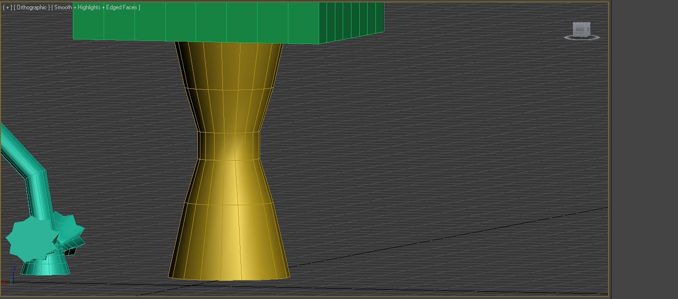
These are planes with a cone shape at the bottom with a cylinder welded on top. This creates the stand or legs for the cubical.
Cubical foot stand:


Welding the cylinder to the leg:

A simple but effective object creation.


Table Creation

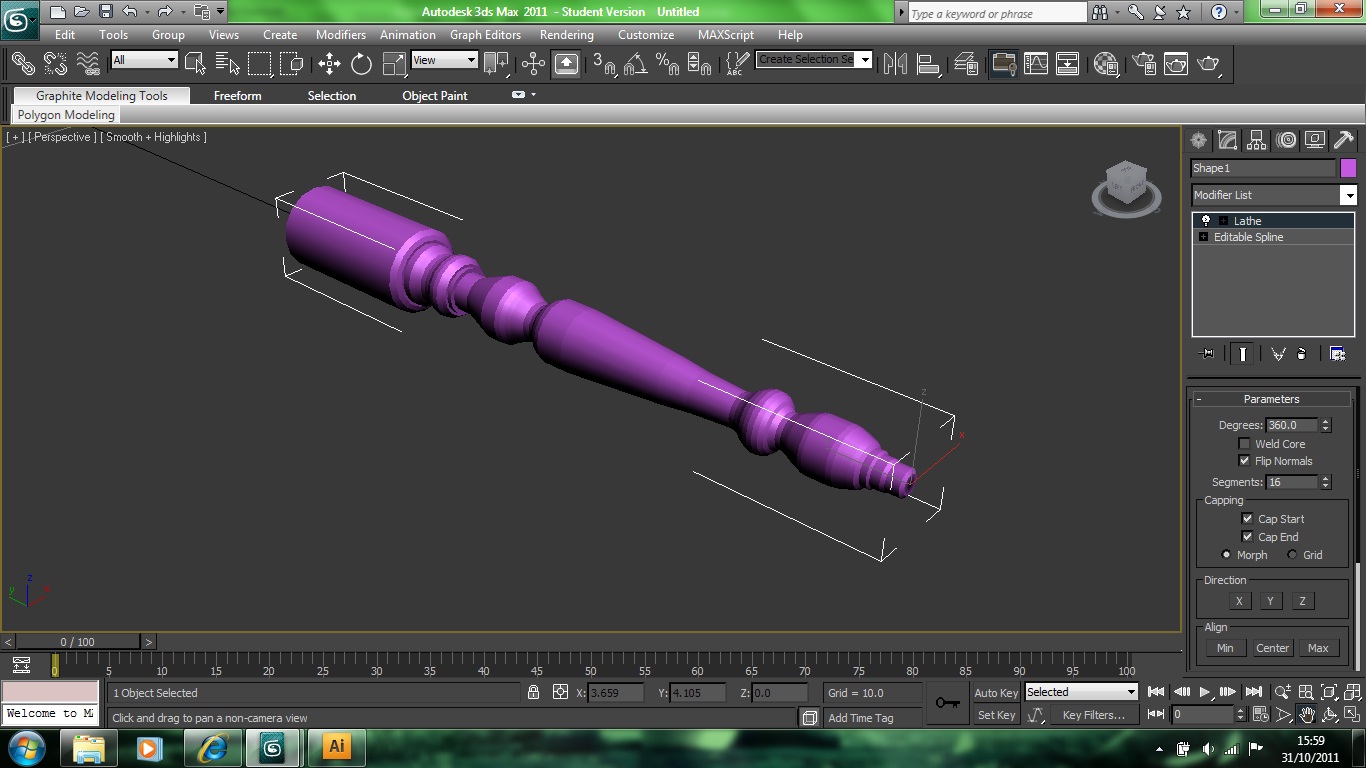
The legs for the table were created first in Illustrator. An image of a table leg drawn around and saved as an Illustrator 3 file.


This was then imported into 3DS Max and using the lathe tool transformed into a 3d object.


The top of the table was created from a box and using the editable poly mode the bottom removed. This enabled me to pull down the edges of the box to create the rim around the underside of the table top. A turbo smooth modifier was then applied and the legs also attached. the table was now ready for importing into the project scene.


Creating the Toilet

The creation of the toilet begun with the creation of two boxes, One to build the top of the  toilet lid and the other to build the water tank.

Smooth modifier was added to the top lid to enable it to look smoother.
The link in the toilet, the connection between the water tank and the seat was created via abox and edited into shape using the editable poly mode.

The toilet seat was created from a Torus shape and flattened slightly with the size tool, this enable it to look more realistic and not so round. The stem of the toilet structure was created by a Torus and shaping it using the soft selection tool in editable poly mode.

The rear of this shape was pulled out to give the effect of a simple S bend in the toilet. The toilet could not be attached together and a mapping material added.


The top of the toilet seat is made from just a flat cylinder and shaped in editable poly mode. This is kept separate from the toilet so I could add a wood texture mapping onto it.

Toilet Rendered:

Creating the Urinal

The urinal was created by a cylinder transformed into an editable poly. Using the vertex points the cylinder could now be shaped into a urinal structure.

Using the cylinder tool once again the water pipe was made. By removing the end polygon and using the size tool I could now stretch out the end vertex points and make the pipe wider at one end.

The pipe was now added to the urinal and positioned. A turbo smooth modifier could now be applied to smooth out the structure.

A marble mapping material was also applied and a stainless steel material for the pipework.  

Floor Plan

The floor and wall structure was created by placing an image of the Guildhall onto a plane. this could now be used as a template in order for me to position the walls into place correctly.

This also provided me with a scale to work with. The images from the Architecture where the images that I used along with these i could get an idea to where windows, doors and stairways would be formed. Of course research from our trip also helped with this.


Door Creation

To create the door I started with a box and converted it to an editable poly. Then using the polygon mode I removed the middle and by holding down the shift key formed the sides where there were gaps. This section would be the door frame.

I then created another box and shaped this to form the edge of the door frame. Using the editable poly tool I removed edges and could weld it to the door frame to create 1 object.
The door itself is another box, placed in the centre of the door frame and using the rotate tool turned into position.

The door handle was created from a cylinder and a sphere; both shaped using the editable poly mode and size tool.

The door could now be applied with mapping materials and imported into the main project scene.
With mapping:
 After importing:


Creating the Disabled Hand Rail

To create the disabled handrail I begun by creating a Torus using the Torus tool. I then converted this to an editable poly and cut the torus in half.

I could now cut the Torus into another half so i had 2 quaters and then stretched out the vertex points of either one of the ends. This was now begining to look more like a handrail.


Using the cone tool I could now create the ends of the hand rail. Using the editable poly in polygon mode I cut off the top so that the vertex points could be welded together. Welding the vertex points can be seen below.


Once the hand rail was welded together it could now be applied with a turbo smooth. this would smooth down the sides and edges to make it look more realistic. A white plastic material was added to the object for colour and material effect.


The hand rail was imported into the scene and placed on the walls of the disbaled and baby changing toilet.


Creating the Chair

To create the chair I downloaded an image from the internet of a typical wooden chair piece that would either support the leg or the backing on the chair.
I then draw around each of the chair legs using illustrator and saved them as a Illustrator 3 file and imported them into 3DS max. Using the lathe tool I then could make the outline of the wooden piece become a whole 3D object.

I then duplicated this 4 times using the clone tool and this created the chair legs.
The seat of the chair was constructed from a cylinder and was modified into shape by editing the vertex points.

The backing of the chair was made in the same way as the leg of the chair using Illustrator and the lathe tool but with a different chair leg from the image.
The top of the chair was created from a box shape and curved via editing the vertex points but with the soft selection tool on.
Once all the sectors of the chair where constructed it was then all attached using the attach tool and a turbo smooth modifier was applied.

The chair was then imported into 3ds Max and aligned with the constructed table.