Monday, 14 November 2011

Roof Creation

The creation of the roof is very simple. It begins with too rectangle narrow boxes welded together at 45 degrees angle. A bitmap is then applied to the roofing to give the interior the impression of a roof tiling effect.

The timber beams are another box constructed by transforming it to an editable poly. In editable poly mode the edges and vertex points are slightly moved about to represent the uneven surface texture of an old beam. A wood texture mapping is then applied. These beams can be seen across the wall construction of the entire building.

Picture Frame Creation

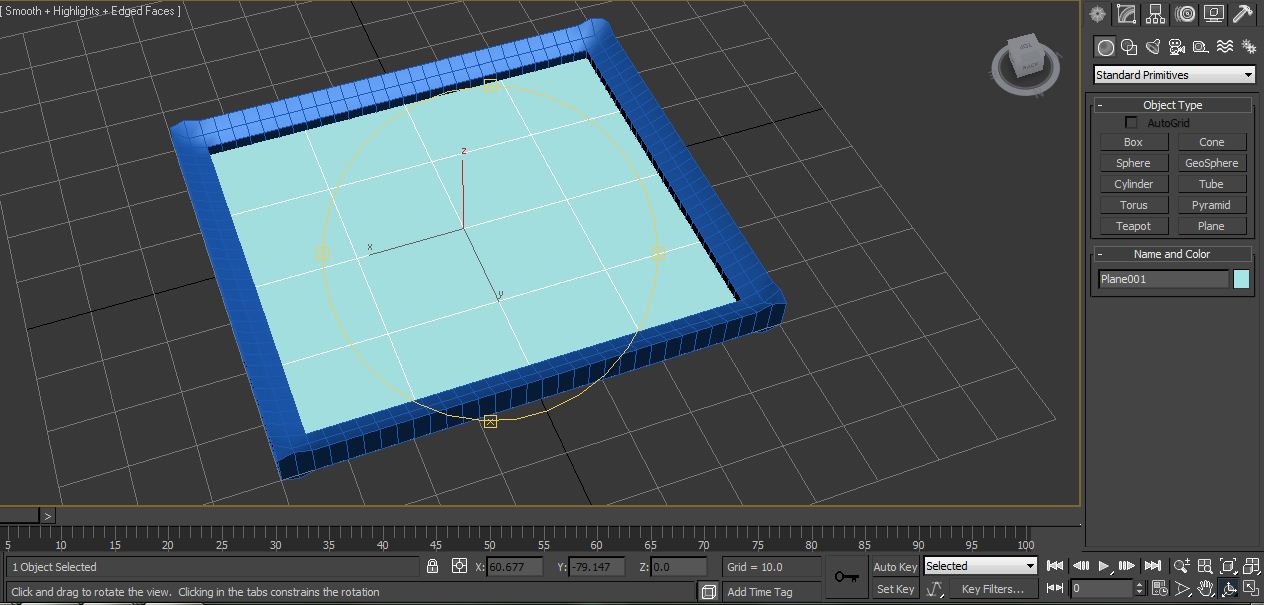
The picture frame was constructed from a box transformed into an editable poly. I ensured that the box had the correct number of edges so that the inner polygons could be removed to develop the sides of the picture frame.  

Now the edges of the picture frame can be pulled upwards and the outer edges of the picture frame pulled up even further.

This now gives the effect of the outside shaping of the picture frame.

A plane is now applied to the backing of the frame in which mapping images can be applied to create the effect of a picture inside of the frame.

An image of a golden frame texture is now applied to the frame to finish off the design.

Lamp Creation

The creation of the lamp begins with the creation of two cones placed one inside of the other. These two cones are then transformed into editable poly’s and the top and bottom removed. The cones can now be welded together to create the lamp shade.


Welding Process:

The bulb is created from an sphere and the holder another sphere added to the bulb. The cable that connects the entire lamp to the ceiling is made from the use of ‘Hose’ tool.
The bulb can now the applied with different colours (black and white) to keep it natural. The bulb can now be grouped together.

The bulb will have a spotlight installed inside the lamp unit so that then it is in the animated scene it will appear as though the bulb is turned on. The positioning of the lighting effect can be seen in the image below.

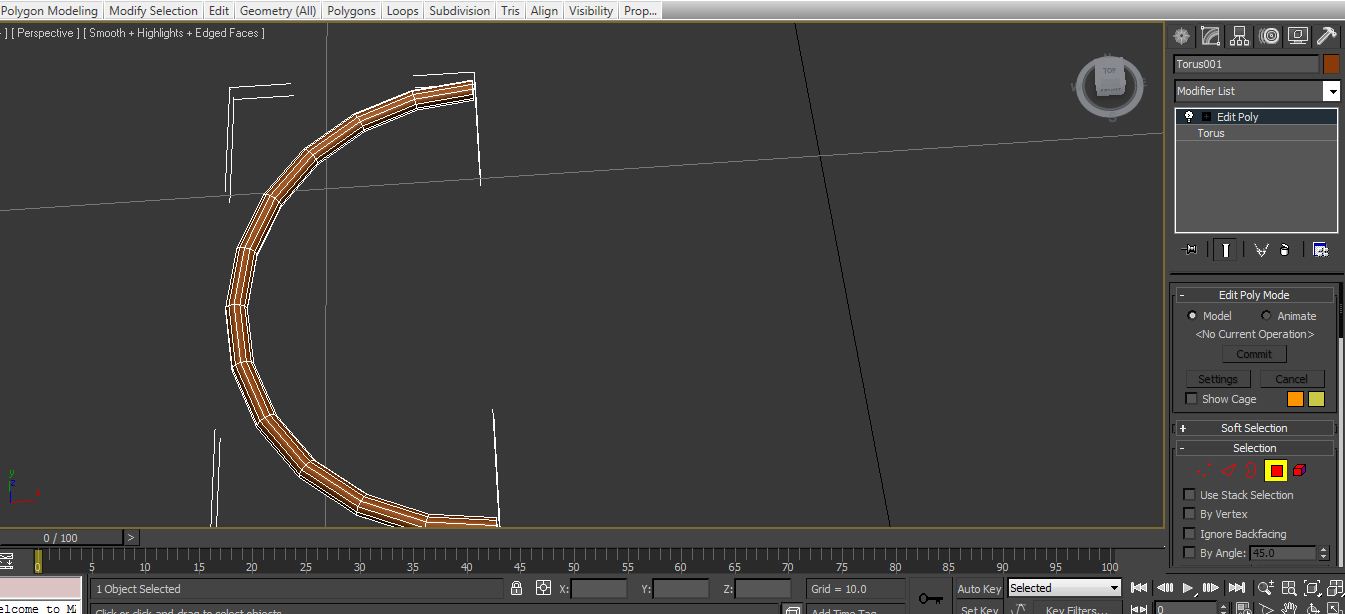
The library lamp is different from the ceiling lamp because it does dangle from a cable. The old original library light found in the current Guildhall is design like the image below. The pipe hold the cable for the lamp and is fix to the wall. It is constructed using a torus and cylinder tools and then welded together to get the right angle in the pipe.


Wednesday, 9 November 2011

Creating the Windows

To create the window and its frame I first begun with a box, then cut out the middle but ensuring that the box would have sufficient vertex points for the next stage of the process.

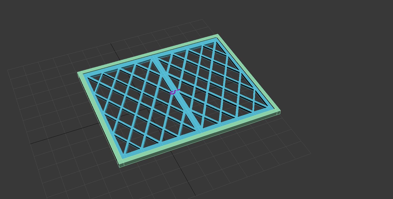
Using another box but in the shape of a long rectangle I cut off each of the ends and duplicated it into any other sizes. This would allow each of the rectangle to fit into the window.

I could now weld the rectangle points into the window frame to give the effect of the lead elements within tutor window period buildings.
Once this was completed I then added  a frame around the window panels and placed glass within them. The glass is a material that has specialised settings to allow the light to travel through it. This material was then added to a plane to give the impression of glass when rendered.

Each of the windows had a handle on the rear to lock and unlock the window, this side would define which way round the window would be facing when placed within the building structure.

I created the window size in 3 different sizes.
·         2 Windows
·         3 Windows
·         4 Windows

The windows were now ready to be imported into the project building scene, it was placed within allocated window sectors that had already been cut out to size.
Allocated Window Sectors:

After Importing:


Creating the Biped Man

To create the biped man I downloaded a man structure already pre-built. This could save a lot of time in the animation and modelling process.
The man was imported into the scene and using the biped tool a biped was created.

The biped was then scaled to the correct size of the man.

To insert the biped into the man I entered the parameters of the biped figure and attached each of the biped components into the man.
Now, using the envelopes sector of the parameters I could now ensure and adjust the envelopes so that all of the man’s limps moved with the biped components.
I had to test each of the envelopes to ensure that each of the limps moved with the biped structure.


Once this was completed I then used Photoshop to edit the material that came with the man. Removing his gun and applying GUILDHALL TOUR onto the front and rear of his clothes.

This is the result of the new biped man that will be used in the animation process of our Guildhall Project.


Creating the Kitchen Units

To create the basics of the kitchen unit I begun by creating boxes using the box tool and placed these into the scene. I arranged the boxes to build up the base and the doors of the kitchen cupboards.

The door handles were created from Torus and cut into half.

The handles could now be applied to each of the doors

The sink that goes in the top of this unit was created from a box, transformed into an editable poly and using the editable polygon mode I could now pull down areas of the surface for the sink to have water basins.

The sink now had to be added to the units but because of its new shape I then cut holes in the unit so that the sink could fit and edges would show through the sink basin. The tap used on this sink was the same tap I created for the sinks that is used within the bathrooms.


The upper units of this kitchen are created from a box and modified to have shelving inside of them in case the doors required to be displayed open.

The cupboards could now be positioned into place.

The oven it created from a box with Torus handles in place and a jpeg image applied to it, this is very effective and looked like a 3d oven.

The hobs for the oven are again a box with a jpeg image on but the hobs themselves are made from cones using the cone tool. This gave them again a 3d appearance.

The kitchen extractor fan is a hexagon modified using the editable poly and another hexagon welded onto the bottom. This enabled the bottom to have the sided effect and be larger than the upper body part.

The kitchen without materials.

The kitchen when materials have been added.


Creating the Stairs

To create the base of the stairs, I first begun with using the stairs tool. Using the stairs tool allowed me to create a set of stairs instantly. Although these are basic stairs.

I then applied a box to the side of the steps on the stairs this gave the stairs definition and made them look realistic.

I then added on the base which was made up of another box and duplicated this process to create the right angle in the stairs.
The stairs looked very plane at this point so in order for it to look improved I decided to add on banister rails. This process was very time consuming and difficult to line up. The banister rails are made up of cylinders sized and cut into lengths.

The ends of the cylinders required welding up using the ‘create’ tool under editable poly, polygon mode.

In order for the stairs to fit the other side of the building, as this stairs was going to be used in two different locations it was necessary to cut the stairs in half and re-position it 90 degrees to the right. I then re-welded all of the components together.

Now a material mapping could be applied and imported and positioned within the scene.


Monday, 7 November 2011

Bathroom Sink and Cubical Creation

The tap on the sink was created from a cylinder that had the bend tool applied and the taps handles them selves were made from a cylinder in editable poly mode with each second edge pulled inwards to give the effect of a tap handle. This components could now be attached together an a stainless steel mapping material applied.

The sink stand was created from a cylinder edited in editable poly mode using the soft selection. This allowed me to bend the centre of the stand inwards.

The sink itself it’s a box with several edges and in editable poly mode, with soft selection mode on the centre of the sink pulled downwards to give the effect of the bowl. A small cylinder added to the centre with a plug mapping applied and UV mapping modifier to give the impression of a plughole.

The pieces of the sink could now all be placed together using the group tool as each component had a different mapping material.


Once imported:

Toilet Cubicles
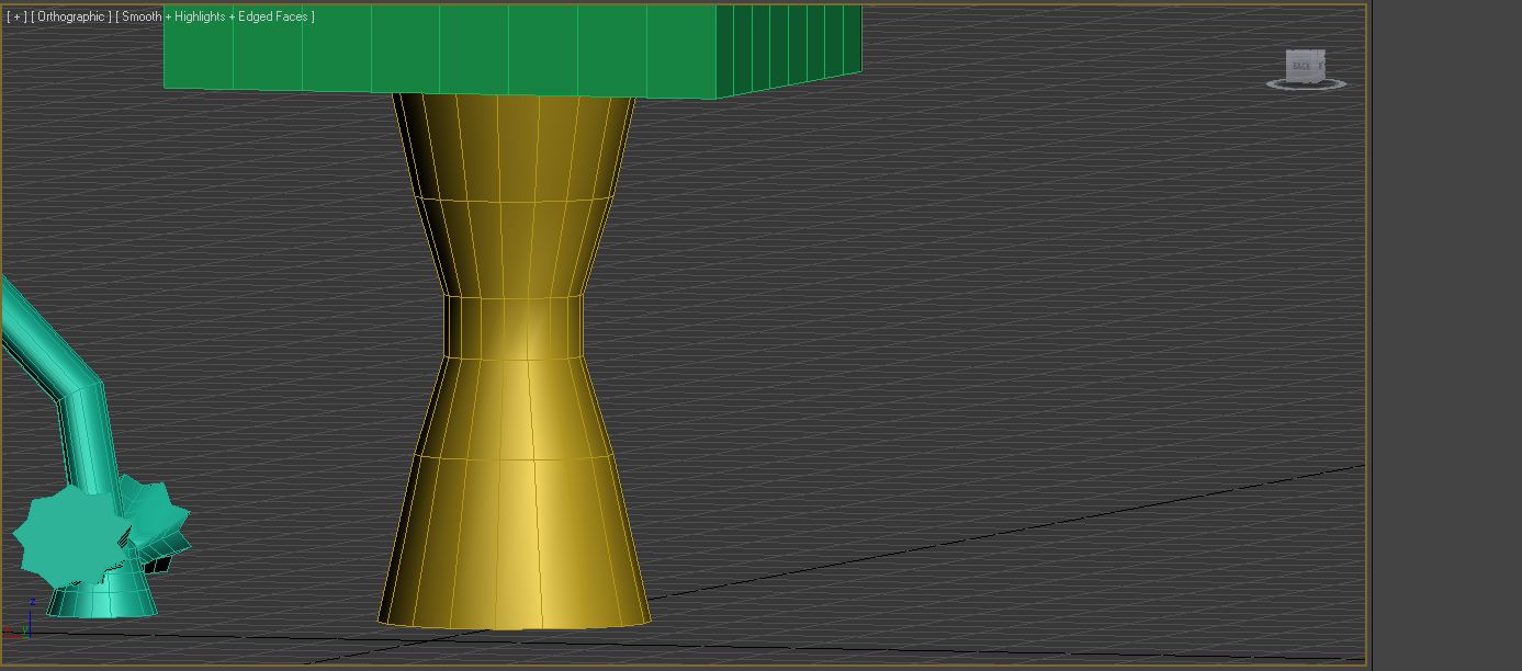
These are planes with a cone shape at the bottom with a cylinder welded on top. This creates the stand or legs for the cubical.
Cubical foot stand:


Welding the cylinder to the leg:

A simple but effective object creation.