Wednesday 7 December 2011

3DS Max Objects Reference List

Below is a list of the only objects that were not modelled by myself, this is due to the short period of time that we had to complete the project.  

Biped Man
3DIVA
Accessed: 25/11/2011
Wall Lamp
3DIVA
Accessed: 25/11/2011

Hall Ceiling Lamp
3DIVA
Accessed: 25/11/2011

Shower Unit
3DIVA
Accessed: 25/11/2011

Monday 5 December 2011

Evaluation

Having evaluated the final project and the rendered video I’m very happy with the results however it has been easy to identify errors and improvements that I could have carried out during the modelling and animation process now that it has been fully rendered and completed.

The time that was allocated to complete the project was a very narrow time slot and this meant that not as much time and detailing could be spent on the modelling process. There are however elements in the modelling objects that represent below my standards of detailing and quality of the objects. This is only in a selected few objects and is perhaps barely noticeable.

I felt that the preparation for this project within the group went very well and it seems that we have stuck well to the storyboard and the mood board features have played a key role in the idea planning.

The modelling stage of the project turned out very well as many of the objects such as the furniture are very well detailed and do represent very realistic life like features. The modelling stages I found were my most favourite as I managed to learn some new skills while creating the models and implemented learnt skills from last year into this year’s creations.  There have been many of my techniques used within the modelling process but time was a big restrictor and as such limited the modelling process methods and quality.

 I felt that the animation techniques that I used in the project have combined very well with the models that I have used. The animation techniques have stuck well to the storyboard and these techniques that I have used appear to function with a high standard. I do feel that I could have incorporated more animation techniques into the project but it was difficult to learn new skills in such a short period. The main new techniques that I managed to learn and incorporate into my work, was the use of the particle flow system. I chose to learn this new skill as it was one of the few that could be used within the educational version of 3DS Max. “Rayfire Techniques” offered much more detailed animation techniques, however this feature is only available to commercial versions or paid plugins which were too expensive to purchase.

The rendering process was a very time consuming section of the project. It was very frustrating and required the use of several computers at any one time in the university. Each of my frames in my animation averaged around 15-20 seconds render time per frame. This is because of the excessive detail incorporated within each of the frames. On some of the computers exporting formats were limited and most of my files appeared to lack some quality. This mainly happened when rendering to AVI format. I had to use the compressed method of AVI because if I rendered in uncompressed it appeared that on some of the computers I lost vital frames which made the video appear poor.

The sound that I have incorporated into my animation is the theme from Alice in Wonderland. I felt that this theme of music worked extremely well with my fly through techniques.

The group worked very well throughout the majority of time but in some stages of the project communication began to lack and it became difficult to keep update to date on the progress of each other’s work. The group’s communication was a vital and essential part of the group project, however towards the end, the group began to pull together better and began to work very well.

The way in which we decided the work should be split up between individuals in the group has work extremely well to everybody’s advantage, as it has allowed all the members in the group to express their modelling and animation skills. It also allowed all the members in the group to have a fair share of work so that no group member put less effort in than another. This encouraged the group to work and function well and work more as a team than a group.

Overall I’m very happy with the outcome of the group project but if only more time was available then the results would have probably been much more improved.

Sunday 4 December 2011

Using the Slice tool

The slice tool is a very simple tool that can be used to reveal objects, cover them or merge them in animation sequences.

I used the slice tool within my animation techniques as part of the wallpaper animation when it was removed in the main upstairs hall.

To begin with I had to apply the slice tool to the wall object that was in the scene, in this case it was the inside wall object.

Once the slice tool had been applied I then had to edit the plane size to ensure that it would flow the correct way and covered the entire wall that needed to be sliced back. Adjustments were made using the size tool and rotation tool .I had to ensure the plane was facing the correct way at the beginning of the timeline.

The image below shows adjustments to the slice plane:

The settings within the slice tool had to be set to “remove bottom” for the effect I was applying it for on the wall.


Using the auto key frame on the timeline I could now create the animation of the wallpaper being removed on the wall. Behind the wall was another wall that had a brick mapping applied. This would give the effect of a bare wall behind the wallpaper.

In the image below you can see the slice tool being used to create the animation. At frame 0 the entire wall can be seen, at frame 70 the entire wall is now removed by the slice tool.

Timeline:


At frame 0:

At frame 35 (half wall):


At frame 70 (no wall):


I found this slice modifier very easy and simple to use and it also created a unique animation effect.

Camera Animation


To create the camera movement animation techniques I first created a free camera onto the scene that I wanted to record the animation. Using a free camera allowed me to use the camera with more flexibility than with a target camera.


To move the camera around the scene to create different screen shots I used the move tool when in perspective viewing mode and the rotation tool. At times this was much easier than using the tools within the camera viewing mode itself.


When viewing the scene through the camera to create minor adjustments it was better to use the movement and zoom tools within camera mode.

The entire camera’s featured and used within the animation, all used a standard lens as I thought that the standard lens was most suitable for all the animation procedures.

To begin using the camera to capture the animations I had to create key frames on the timeline using a combination of the auto key frames and manual key frames, this is because using auto key frames would sometimes make the camera move in ways that weren’t necessary. Moving the camera through each of the key frames allowed the camera to flow through the scene and capture what I needed to render.


Friday 2 December 2011

Biped Walking Animation and Physical Movements


To create the biped walking animation I begun by using the rigged biped of the man that I had created earlier in the semester.
I imported the biped onto the scene and then began to position the biped’s where I wanted them, such as in rooms, doorways etc.

I had to ensure that the camera would pick up the walking biped people in the correct frames. To ensure this happened I made sure that the cameras and biped would meet at the correct frames on the timeline.
To make the biped walk I used the automatic walking tool within the biped features. By selecting the footstep mode I could then create footsteps within the scene, I could use the option to create as many footsteps as necessary.

Once the footstep were created I could then position each of the footsteps in the correct location to make the biped walk through doors, turn corners and walk down stairs.


The biped automatically created frames along the timeline, so in order to make the biped grad door handles when walking through doors I had to position the biped’s hands on the door handle in the correct frames.

This was easiest in auto key frame mode. This process was used for the smoking kettle scene and walking through the toilet door scene.

These effects can be seen in the rendered images below:
RENDERED IMAGES HERE

Creating the Particle Flow System (New Learnt Technique!!)

(New Learnt Technique!!)
This technique is very new to me as I have never been introduced nor learnt anything about the Particle flow System up until now. To create the particle flow system I first had to create an object. This could be anything so I decided to place it on a box at first. Later I would then apply it to other objects.
To open the particle flow can be done either with pressing ‘6’ or using the navigation tools at the top of 3DS max.

Once in the scene I then selected the particle flow standard and placed it on the board. Going into the birth settings allowed me to edit the start and end time of the particle flow.

To add the box to the particle flow I then opened the object section and used the add tool to add the box.

Adjusting the shape and size of the particles could be done using the display and shape modifiers.
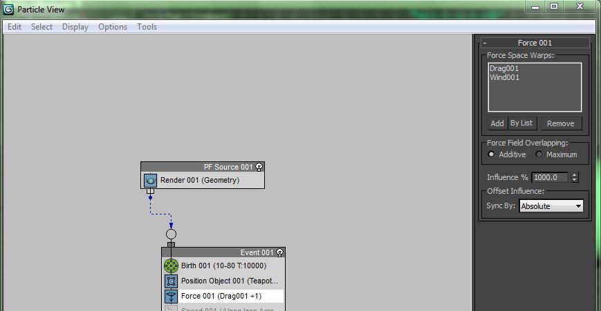
On the scene it was necessary to apply a wind modifier and a drag modifier. These could now be applied to the particle flow system by adding a force event to the board.

Within this force event I could pick the wind and drag forces on the scene.

These forces would allow the particles to travel in the direction of the wind to give the effect of the particles blowing off the object.

To adjust the speed and strength of the wind I could do this by adjusting the settings within the modifier panel of the wind force itself on the scene. The wind force was set to a slow pace of 1.0 and turbulence to just 0.5. This will give the particles a slow effect and a slight random amount of turbulence when they appear to be removed from the object.
Now the particle flow system works on the object.
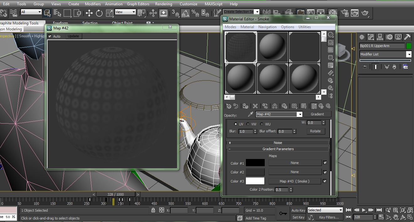
However the object needed to disappear. This was done by creating a fade effect on a material so that as the particles flowed from the object the fade would slowly disappear the object. This was done by opening the material panel and creating a material that could fade by first creating a mulit object material, only 2 materials within though.


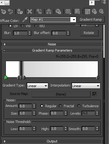
Next to apply a gradient ramp to the particle material and editing the key frames to make the particles change as they drifted away. This was done by crating key frame with the auto tool and changing the colours and frame in the gradient ramp parameters.

The same thing was done to the box material but instead of the material fading across it would fade completely out. This was done using the same technique but applying the gradient ramp to the opacity instead of the diffuse, same procedure as above but as the colour continues to go completely black as the timeline continues along.

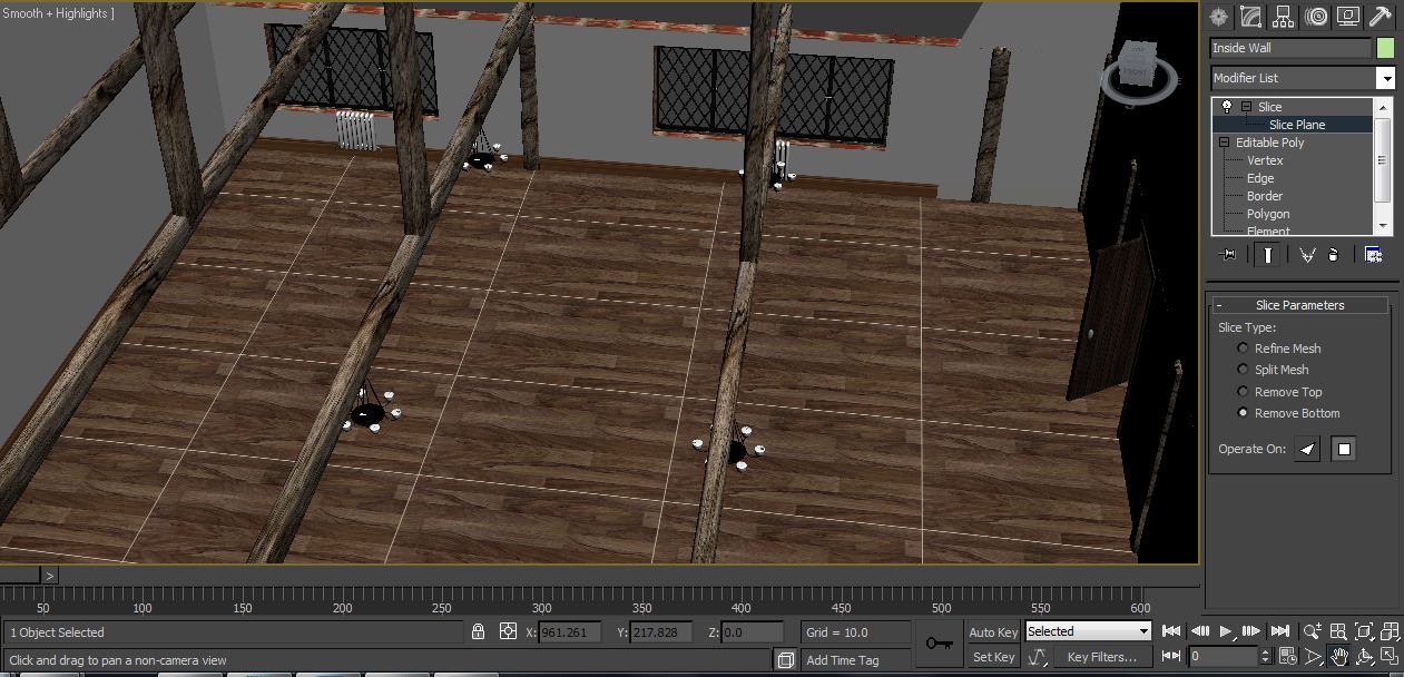
This could ow be applied to the object which has the particle flow system installed on it. 

This technique was then applied to the light within my animation scene:

And the Radiator:

Kettle and Smoke Animation


To create the Kettle and smoke animation technique I first began with using the tea pot tool from the creation panel then created a teapot on the scene within the kitchen.

To create the smoke on the kettle I had to use a superspray selected from the compound system in the object creation panel.

To create the superspray into a form of smoke I had to adjust the settings within the superspray as follows:
Icon Size: 10
Percentage 6%
Particle Speed: 8
Particle Size: 14
Emitting Start: 0                End: 1000
Particles: Facing
Rotation: Random
Spin Time: 20

After applying these settings it was then necessary to create the material for the smoke. The material is the most important section of the smoke as without this the smoke cannot be seen properly when rendering.

To create the smoke I opened up the material panel and selected a material changing the default name to smoke.  I had to drop the gloss to 0 and change the colours of the diffuse and ambient to a slightly dark grey. Then I applied a gradient modifier to the Opacity and a smoke modifier within this gradient.


Within the smoke modifier I had to change the colours to a dark black. This would make them fade off when rendering. Changing the size to 5 and literation’s to 4. I could now come out of this and go to parent and making sure the ‘check’ face map box was ticked, I then changed the ‘blinn’ to a Oren Nayar Blinn. Now the smoke material was completed it could not be applied to the superspray.


Now that the smoke is applied to the superspray, this can now be connected to the teapot using the link tool.

I then added the kettle to the biped that had been placed in the scene and linked the kettle to the biped’s hand. With auto key frames on I could now move the bipeds hand and make it look as though the biped is moving the kettle with his hand and the kettle is smoking.


Creating the old version of the building

Once I had created the new renovated building of the guildhall it was a lot easier to change the building than create a new one from scratch. To begin with I striped everything out of the building and saved it as a new file.
Using and editing the walls in edit poly mode I could now adjust the vertex points and reposition the walls with reference to the architecture drawings.
Once this had been completed I could now section off each of the walls using the polygon mode and the detach tool. This enabled me to separate the polygons in each of the rooms so that I could apply different colours to the walls and different wallpaper designs.
Most of the objects that are within the old building have been imported from the new renovated complex and possibly in some areas modified. If any modifications on the objects have occurred this is purely so that it is compatible with the building structure that surrounds it.

Right Side:


Left Side:

Once all of the walls had been changed and coloured modified and all of the new materials within the building, it could now be used to create animations.

Images of the old building before renovation can be seen below:

Kitchen:


Lounge:


Bedroom:


Stairwell:

Wednesday 23 November 2011

Walls and House Structure

The development of the structure of the house begins with creating planes in order to hold the images of the Guildhall hall. This image is what was used in order to align the segments of the walls with.

The main structure of the house is created from boxes. These boxes are then welded together by cutting through sections of the polygons so that each of the boxes can be welded together. This structure is used throughout the entire modelling process to create the structure of the walls, rooms and doorways etc.

Creating the planes:


Creating the walls:


Welding the walls and dragging out edges. Using the border and holding down shift key enables me to pull out walls and adjusts where necessary:


Making doorways:


After sometime spent of modelling parts they can now be implemented into the rooms of the house:


Below in the images you can now begin to see the development of the toilets and the bathrooms:


Now the doors can begin to be installed into the doorways. This allowed me to see where things were going to be structured and how much room I would have in each of the rooms. Doors and there housing were duplicated using the shift tool. This is the same process used for all of the objects that required duplication.

Now i had created this part of the modelling building struction it was now time to begin to create the development of the final project building model. This meant pulling the walls into the correct scale and developing the rooms to become seperate objects. This process was done by selecting the polygons in each of the rooms and using the detach tool in editable poly mode so I could seperate each of the polygons. This meant that I could now apply seperate wall papers to each of the walls and modify them individually.

Each of the rooms were named so that they could be selected using the select by name tool within 3ds max when necessary.

Using the move, rotate and scale tools and mainly editing in editable poly mode with polygons, edges and vertex points, the walls and rooms slowly progress into a completed project structure. Now the main features such as lights and furniture could be added to the building the begin to become closer to the animating stages of the project.

Upper Floor Modelling Stages:

Left Side -


Main Hall -


Right Side -


Underside -


This is much further into the development process of the upper section of the house. After creating all of the modelling on the objects they can now be implemented into the structure of the house. Bitmaps are now applied to the walls and flooring and all of the objects to give a more realistic look.
These sections below are taken from the NEW Guildhall Building -
Upper landing of the House:


Main Upper Guildhall Room:


Upper stairways, right section of building:

New Kitchen:

New Bathrooms:


Stairway: